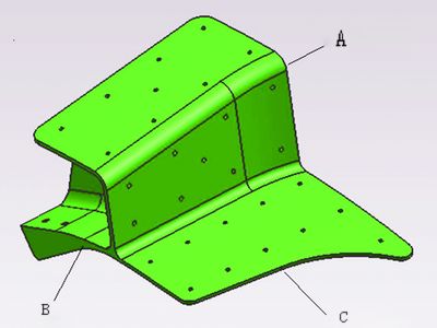
This section introduces aerospace structural components manufactured by the company. These parts are classified as thin-walled and difficult-to-machine components (see Figure 1). The thinnest section measures 2.5mm, made from 7050-T7451 AMS4341 material. The minimum containment size is 180mm × 95mm × 123mm, and a surface roughness of Ra = 3.2 μm is required.

Figure 1
Process Analysis
(1) Except for two sides (see Figures 1A and 1B), the rest of the part consists of parallel planes and curved surfaces. The small holes on the curved surfaces are standard through-holes. Notably, the contour at side C is perpendicular to the adjacent surface, which necessitates five-axis simultaneous machining.
(2) The wall thickness of the part is very thin, with a surface contour requirement of 0.5mm. At the right end of the C contour, the wall thickness is only 2.5mm, resulting in low rigidity. This makes it critical to avoid vibration and tool chatter during the machining process.
(3) Most of the part features curved surfaces, making it challenging to locate and clamp during CNC machining. Therefore, the digital milling process requires a process chuck that provides both a positioning reference and a reliable clamping plane.
2. Five-Axis Milling Processing Solution
To address the challenges of clamping and positioning, two processing schemes were developed.
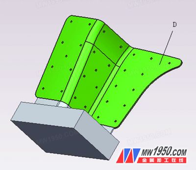
(1) A process chuck was mounted on the end face of the part (part A). The chuck was clamped using a vise, and the remaining areas were machined. Finally, wire cutting was used to remove the chuck along the end face of A. The setup of the chuck is shown in Figure 2.
The advantage of this approach is that it allows five-axis machining to complete multiple faces of the part in one operation, reducing positioning errors caused by repeated clamping. It also simplifies pre-processing preparation since no special tooling or fixtures are needed. However, the downside is that the five-axis machining workload is high, leading to increased costs in mass production. Additionally, the D area in Figure 2 is poorly machined and prone to vibration.

Figure 2
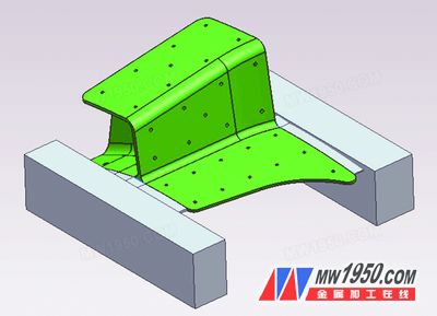
(2) Process chucks were placed on both end faces of the part, with positioning holes created on the chucks. These holes served as the sole reference for multiple clamping operations. The chucks and parts were designed to be thinner at the joints, allowing them to be removed using a conventional milling machine. The chuck setup is illustrated in Figure 3.

Figure 3
This method effectively addresses the rigidity issues encountered in the first solution, particularly in the D area. The part can be clamped multiple times on a three-axis machine tool, significantly reducing processing costs. However, the drawback is that removing the chucks involves more manual work, requiring higher operator skill.
After comparing the two approaches, it became clear that the second method is more cost-effective, practical, and carries lower implementation risks. As a result, we opted for Option 2.
3. Process and Machining
(1) The material used is an imported aluminum alloy sheet, costing approximately $4.75 per pound. Due to its high material cost, which constitutes a significant portion of the total cost, we employed nesting processing based on the part’s contour shape, as shown in Figure 4. To accommodate the process chucks on both sides, the square material size was set to 280mm × 194mm × 110mm. Wire cutting was used to cut along the part’s contour in two "L" shapes, allowing each piece to produce two finished parts.
(2) After cutting, the blank was processed on a three-axis machine. The first step involved positioning the reference surface and hole located on the process chuck. A pressure groove for the upper bolt was also machined, as shown in the figure. The part was then clamped using a vise, and the top surface was milled flat with a scalloped cutter to ensure a flatness of 0.02 mm. The positioning holes were machined to f10H8 with a spacing of (178 ± 0.03) mm between them.
In the sample processing phase, after machining the two positioning holes and the pressure groove, the remaining rough and finish machining was performed on a five-axis machine. Since five-axis machining is much more expensive than three-axis machining, we optimized the process to maximize the use of three-axis machines, significantly reducing the overall cost. The specific machining route is outlined below:
Three-axis milling: First, the process contents shown in Figures 6–9 were machined by positioning the bottom surface and the two holes. Step 40 involved positioning the step surface processed by the two positioning holes and steps 15 and 20, as illustrated in the figure. The joint between the part body and the process boss was 2mm thick and extended 12mm at positions A and B for subsequent cutting. During the 15th process, when machining the open cavity on the side, an undercut surface was present in the machining direction, as shown in the UG draft analysis. This area could only be machined on a five-axis machine.
For more details, please download the attachment or refer to Metal Processing (Cold Processing), Issue 15, 2013:
Smart Downlight,Wifi Smart Light Bulb,Led Smart Emergency Bulb,Smart Emergency Bulb
JIANGMEN MOSCOT OPTOELECTRONIC TECHNOLOGY CO.,LTD. , https://www.sensorsled.com