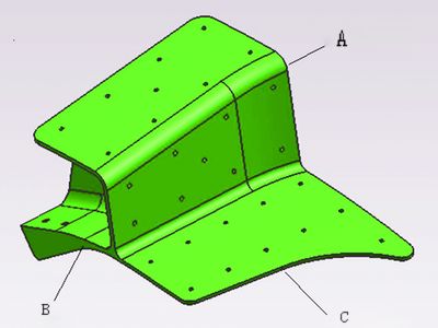
This section introduces aerospace structural components manufactured by the company. These parts are classified as thin-walled and difficult-to-machine components (see Figure 1). The thinnest section of the part is only 2.5mm, made from 7050-T7451 AMS4341 material. The minimum containment size required is 180mm × 95mm × 123mm, and the surface roughness must meet Ra = 3.2 μm.

Figure 1
Process Analysis
(1) Except for the two side surfaces (as shown in Figures 1A and 1B), the rest of the component consists of curved surfaces. The small holes on these curved areas are standard through-holes. Notably, the contour at side C is perpendicular to the adjacent surface, which necessitates five-axis simultaneous machining to ensure precision and alignment.
(2) The wall thickness of the component is very thin, with a contour requirement of 0.5mm. At the right end of the C contour, the wall thickness is only 2.5mm, resulting in poor rigidity. This makes it challenging to avoid tool vibration during the machining process, requiring careful selection of cutting tools and techniques.
(3) Most of the part is composed of complex curved surfaces, which significantly complicates the clamping and positioning in CNC machining. Therefore, in the digital milling approach, a custom process chuck is essential to provide a reliable reference point and secure clamping area for the workpiece.
2. Digital Milling Processing Solution
To address the challenges of clamping and positioning, two different processing schemes were developed.
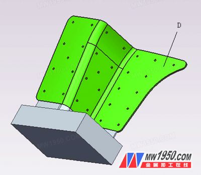
(1) A process chuck was mounted on the end face of the part (Part A). It was then clamped using a vise, and the remaining areas were machined. Finally, the chuck was removed via wire cutting along the end face of A. The setup of the chuck is illustrated in Figure 2.
The advantage of this method is that it allows five-axis machining to complete multiple faces in one operation, reducing the risk of positioning errors caused by repeated setups. Additionally, it simplifies pre-processing preparation, as no special fixtures or jigs are needed. However, this approach involves a high workload for five-axis machining, leading to higher costs in mass production. In Figure 2, the D area is particularly difficult to machine and prone to vibration.

Figure 2
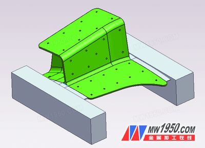
(2) Process chucks were installed on both end faces of the part, with positioning holes drilled into them. These holes serve as the sole reference for multiple clamping operations. The chucks and parts can be designed to be thinner at the joints, allowing for removal using conventional milling machines. The chuck arrangement is shown in Figure 3.

Figure 3
This scheme improves the rigidity issue found in the first solution, especially for the D area. It allows the part to be clamped multiple times on a three-axis machine, enabling most of the machining to be done without the need for expensive five-axis equipment. While this reduces overall processing costs, it requires more manual effort in removing the chucks and demands a higher level of operator skill.
After comparing the two methods, the second option proves to be more economical, practical, and lower in implementation risk. As a result, we opted for Option 2 for production.
3. Process and Machining
(1) The raw material used is an aluminum alloy sheet, costing approximately $4.75 per pound. Given the high material cost, nesting processing was employed to optimize material usage based on the part's contour. The square material size was set to 280mm × 194mm × 110mm to accommodate the process chucks on both sides. Wire cutting was then used to cut along the part’s contour in two "L"-shaped pieces, allowing each piece to produce two finished parts.
(2) After cutting, the blank is positioned using the reference surface and hole on the process chuck. A pressure groove is also created for clamping with a bolt. The vise is used to hold the part, and the top surface is milled flat using a scalloped cutter to achieve a flatness of 0.02 mm. The positioning holes are machined to f10H8 with a spacing of (178 ± 0.03) mm between them.
In the sample processing stage, besides machining the two positioning holes and the pressure groove, the rough and finish machining of the remaining areas is carried out on a five-axis machine. Since five-axis machining is significantly more expensive than three-axis machining, we optimized the process plan to use the three-axis machine as much as possible, which greatly reduced the overall cost of the part.
The specific machining route includes: First, the process contents shown in Figures 6 to 9 are machined using the bottom surface and two holes as references. Step 40 involves positioning based on the step surface processed by the two positioning holes and steps 15 and 20, as shown in the figure. The joint between the part body and the process boss is 2mm thick and extends 12mm (at points A and B) for subsequent cutting. When machining the open cavity on the side in the 15th process, there is an undercut surface in the machining direction, as analyzed in the UG draft (see Figure 11). This area can only be machined on a five-axis machine.
For more detailed information, please download the attachment or refer to Metal Processing (Cold Processing), Issue 15, 2013:
Recessed LED Downlight with built-in Microwave Motion Sensor
| Model | AM-6.0GY |
| Luminous flux | 800~900lm |
| Luminous Efficacy | >80lm/W |
| Colour Rendering index | 80 |
| Beam Angle | 140° |
| Light Decay | <30% over 10,000 hours |
| Rated Lifespan | >30,000 hours |
| Power consumption | 10 watts |
| Input voltage / Frequency | 80-260vac 50-60HZ |
| Reflector / Diffuser | Frosted diffuser |
| Operating Environment | -20°c~+50°c |
| Dimensions | Φ193*77mm |
| Hole Cut Size | Φ160~Φ180mm |
| LED Source | 56pcs SMD2835 |
| Working mode | ON/OFF or Full/Dim |
| Sensor Range | 180*360 degree |
| Sensor Distance | 6-8m Radius |
| Delay Time |
18-25s |
Solar Power,Solar Portable Power Station,Solar Power Panels,Solar Portable Power Station Camping
JIANGMEN MOSCOT OPTOELECTRONIC TECHNOLOGY CO.,LTD. , https://www.sensorsled.com