The tooth profile of a certain product of our company needs to be shaped once by a forming cutter (as shown in Figure 1). The back of the conventional forming cutter is realized by reciprocating cutting of the shovel lathe, but the forming cutter has a width of 40 mm, and the contour contour and dimensional tolerance requirements of the knives are relatively high. If machining with a shovel-toothed lathe, many knives must be made to transfer the machining, and the transition of the arc-shaped surface of each section can be detected by the board. Since the tolerance of the profile of the tooth surface of the product is relatively high, the tooth-tooth turning The production of the knife is far from satisfying the requirement of the tooth forming of the product at one time, so this solution can only be stranded.
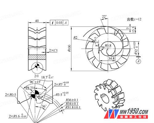
Figure 1 Forming cutter
Another solution of the company decided to find a professional tool manufacturer to customize the tool . After half a month, the foreign tool was purchased and returned to the factory. After careful observation, we found that the back of the tool was formed by CNC grinding machine programming, and the back showed a multi-segment wave shape (the grinding wheel was shaped by grinding, see Figure 2 ), the dimensions and tolerances of the cross-section shape and measurement of the measuring room meet the design requirements, and the 12-tooth round jump is 0.03mm. The overall production precision is ideal. After trial production in the workshop, the processed products meet the requirements of the process, and also expose a major drawback of the tool : because the cutting edge width is only 0.1mm, the tool wears faster and needs frequent grinding. However, the existing equipment of our factory can't be repaired on the back, and it must be handed over to the manufacturer to use special equipment for grinding. It is very time-consuming and far from meeting the mass production needs of the workshop.
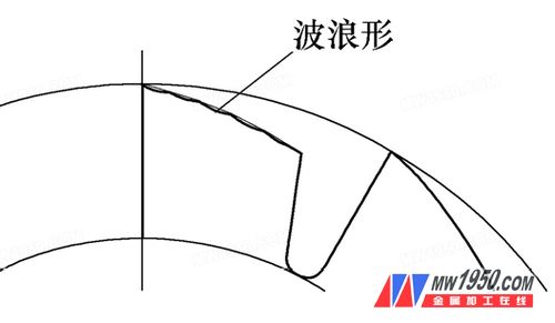
Figure 2 Outsourcing tool back profile
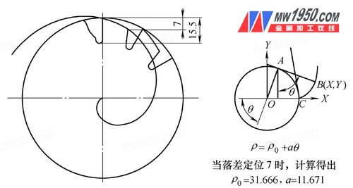
Figure 3 Archimedes spiral calculation
Considering the large output, tight time and heavy task, the company decided to tackle the project. After discussion, it decided to change the traditional process and use CNC milling to process the back of the knife. The first problem encountered is to accurately draw a perspective view of the tool . After consulting the data, it is determined that the rear projection trajectory of the tool is an Archimedes spiral (ie, a constant velocity spiral) because the back of the constant velocity spiral has any The cross section of the center has the same angle after cutting, and the grinding angle can be cut again by grinding the rake angle. At first, the single-tooth design drop is 5.5mm according to the traditional standard. According to the Archimedes spiral polar coordinate equation Ï=Ï0+aθ (see Figure 3), Ï0=35.679, a=9.435 is calculated. Finally, using the point method, a regular set of continuous coordinates is calculated, and a complete three-dimensional view of the forming tool is accurately drawn using SolidWorks (see Figure 4).

Figure 4 perspective view of the forming cutter
The second is the machining of the tool . First, the CNC car turns the size of the rotary body of the cutter section into position reduction. Then, on the CNC milling XT-650 workbench, the indexing head is installed to divide the tool into equal parts. In order to ensure the accuracy of the knives of the rake face, the rake face is finished by 0.1 to 0.2 mm for each indexing. The CNC personnel used PowerMILL 9.0 to program the back of the tool , and through several simulations of different tool paths (see Figure 5), the tool path for roughing and finishing was finalized. The software simulation process observation effect is ideal, so the programming is started, and a forming cutter is produced in less than 3 hours of continuous cutting. The forming cutter meets the process requirements through the measurement room.
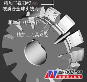
Figure 5 Forming Milling Machining Simulation
Through the first round of the trial production of the product, the shape of the forming cutter processed by this method basically meets the shape and size requirements, but the surface roughness of the processed product is poor. After research, it is found that the tool has a rounded beat. Large (maximum beat is 0.08mm). In order to reduce the runout, we improved the process. The second-round forming cutter first processed the shape and the inner hole of the tool before the heat treatment. The surface roughness of the product in the front workshop was improved, but it still could not meet the requirements. The technicians brainstormed and finally discovered the essence of the problem. The small drop of the traditional constant velocity spiral caused the tool to have a small back angle. During the milling process, the chip removal was not smooth, and the friction between the chips and the product caused the surface roughness of the product to be inconsistent. . Therefore, after further reviewing the literature, after deep understanding of the characteristics of the constant velocity spiral, the third round decided to change the original drop 5.5mm to 7mm, and the parameters of the constant velocity spiral were calculated as Ï0=31.666, a=11.671. It is found by calculation that the back angle of the tool is increased from the original 17° to 21°. The tool processed according to the back angle is tested by the front workshop, and the processed product is qualified, and the surface roughness is obviously improved. Compared with the purchased tool , the size and surface roughness of the product are basically the same, and the frequency of the grinding tool is increased from 200 pieces/time to 800 pieces/time, which is 4 times that of the purchased tool , and the grinding is very convenient. It can be repaired in about 15 minutes, saving a lot of time for the successful completion of the product task.
Through the trial production of this type of knife, the company has explored a new way to process complex tools . The process plan can effectively improve the processing precision and production efficiency of complex section-shaped knives, and the economic benefits are remarkable.
Steel Grating plate is
made of high quality steel plate after bending machine, made after punching,
sturdy and durable, easy to install, galvanized after the installation of a
beautiful folder, and not rust, can be a good fixed installation folder.
The installation of the steel grating can be fixed by
welding and mounting fixture fixed in two ways. Welding fixed for permanent
removal of the site, such as the equipment around the platform, and the use of
the installation folder does not damage the zinc layer and easy to remove the
characteristics.
The mounting clip is suitable for all kinds of steel
gratings, which consist of upper card, lower card and M8 bolt. Welding fixed
method is: in the steel grating each corner of the first flat steel, the weld
length of not less than 20mm, high not less than 3mm of the fillet weld.

Steel Grating Mounting Clip, Stainless Steel Mounting Clip, Galvanized Mounting Clip, Carbon Steel Grating Clip
Hebei Zhenxing Jinyuan Wire Mesh Group Co.,Ltd , http://www.zxsteelgrating.com