The film ç‘•ç–µ online detection system is used to detect common defects such as stains, mosquitoes, holes and impurities on the surface of various film products during the production process. The system can timely discover the defects on the surface of the product during the production process and reflect the surface of the production line in real time. The defect information, and the ç‘•ç–µ classification process, completely replace the artificial naked eye for sputum detection.
First, the design requirements
1. Detection object
The mobile phone uses a gray-black opaque film with a width of not more than 1000 mm and a thickness ranging from 0.2 to 0.5 mm. The thickness of each film to be inspected is uniform, and the line speed is not more than 25 m/min. As shown below:
Movement speed: 25 m / min ≤ 1 m

Figure 1 Schematic diagram of the detection object
2. Testing requirements
a) Test format: 1000 mm.
b) Detection speed: 25 m / min, which is 417 mm / sec.
c) Detection capacity: holes with a diameter of ≥0.1mm.
d) Within the range of system detection capabilities, when holes are found, they can be marked with quick-drying ink at the hole location and marked on the axial side of the winding.
Second, the design plan and feasibility analysis
The system uses machine vision technology to detect the film quality. The machine vision detection system generally consists of the following parts: lighting unit, camera unit, image acquisition unit, image processing unit, computer, display unit, execution unit and alarm unit, as follows The figure shows. To ensure the final detection capability of the system, the design of the imaging system is critical. The following is the design and equipment selection for each link.
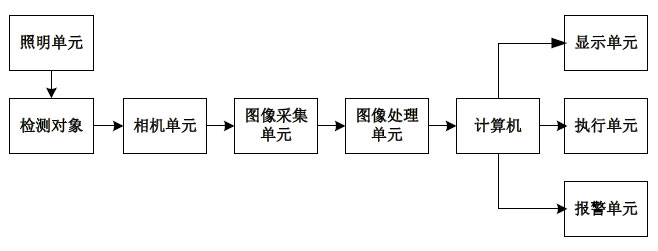
Figure 2 Block diagram of the machine vision system
Light source illumination
In the defect detection, two kinds of illumination methods are commonly used: one is reflective and the other is transmissive, as shown in the following two figures.
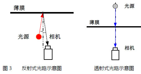
Although both methods can image the holes, the imaging effect of the holes is quite different. A good imaging system requires distinctive features and high contrast. When the hole is small, the holes in the reflection-formed image are close to the gray scale of the film, which is difficult to find. Since the detection object is a gray-black opaque plastic film, the film has no light irradiation under the transmission illumination mode, and the image gradation is very low; only the light at the hole can be transmitted through the CCD target surface, the image gradation is very bright, and the film image is The difference in gray scale is significant, which is very helpful for detection, as shown in the figure below. Therefore, it is recommended to use transmissive lighting.
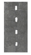
Figure 4 Example of a transmitted image
In the transmission imaging mode, the influence of the light diffraction phenomenon is taken into consideration. Diffraction generally occurs when the wavelength of the light source and the diameter of the hole are comparable. The wavelength of visible light ranges from 380 to 780 nm, which is much smaller than the diameter of the hole. As long as the laser source is not used, the diffraction phenomenon will not be severe. Even if there is a slight diffraction phenomenon, the hole image will be slightly larger than the actual hole, which will facilitate the hole detection. When the position of the hole is located, since the diffraction phenomenon occurs uniformly on the contour of the hole, the positioning of the hole is not affected.
In addition, to use a dense light design, use the box to wrap the imaging light path to reduce the impact of other surrounding light sources. Measures such as extinction teeth, blackening, and light bar are added to the cabinet to further reduce stray light at the entrance of the light path.
2. Light source
The light source is the key to the system design. It is the reference signal of the system, and the target signal will be modulated on the reference signal. The requirements for the light source are stable, uniform, strong anti-interference ability, and long half-life. Both the transmissive and reflected light sources must ensure uniform illumination of the imaging area, proper illumination, and the required length of the light source to cover the full field of view. In consideration of these requirements, the light source can only use a linear light source. Due to the use of transmissive illumination, there is no special requirement for the spectral range of the source, as long as it is visible in the visible spectrum.
Considering that the detection area is wide, 1000mm, there are two kinds of light sources to choose from, one is the high-frequency linear sunlight source, and the other is the LED light source.
The high-frequency linear solar light source has a life of about one year, high brightness, uniform light field distribution, and low price. A high frequency electronic ballast is required. The main parameters are as follows:
Table 1 High-frequency linear light
Source parameter name | parameter |
Spectral range | 450-700 nm |
life | ≥2000 hours |
length | 1000mm |
Quantity | 1 |
The LED light source has a long life and a stable light intensity, which can be strobed with a high frequency pulse signal, but the price is relatively expensive. The main parameters are:
Table 2 LED light source parameters
name | parameter |
model | |
Uniformity | 10% |
stability | 1% |
Spectral range | 450-700nm |
power | 6.6W/12V |
life | ≥10000 hours |
Dimensions | 1000mm |
Quantity | 1 |
Considering both, quality can be guaranteed in terms of imaging, and price and longevity are factors that need to be measured. If the system cost control requirements are high, it is recommended to use high-frequency linear sunlight source; if the cost is not high,
For equipment maintenance and maintenance requirements, it is recommended to use LED light source.
3. Detecting the width
The effective width of the object to be tested is 1000 mm. Considering the small range of oscillation and deviation that may occur during the movement of the film, it is not possible to design only according to the effective width, but to consider the amount of the frame. The design deviation width is set to 1020mm by using 10mm on each side as the design deviation margin.
4. Pixel resolution
In the design requirements, the geometric detection capability of the hole is required to be 0.1 mm, and the geometric resolution is converted to the relationship of 1.6 to 2.5 times of the resolution of the pixel, and the resolution of the pixel needs to be 0.063 to 0.04 mm. Considering the contrast between the hole and the film when the transmission imaging is very different, according to the mature project experience of the new technology, the cell resolution of 0.063mm can meet the detection requirements.
Since the design of the system detects a width of 1020 mm, the number of required pixels is 16190. 062毫米。 The number of pixels of the high-resolution camera is generally 1K (1024), the number of pixels of the system is designed to be 16K, the actual resolution is 0. 062mm.
5. The design of the test object has a width of 1020mm and a displacement of 417mm per second in the longitudinal direction. Therefore, the image size to be processed per second is about 16K×6700. It has a large field of view and high resolution. It is not suitable for use. The area camera is tested. If you use a 2K2K high-resolution area array camera, you need at least 24 cameras to meet the requirements. The cost of the camera will be very high, it is not easy to install and debug, and it is difficult to achieve the whole view due to the large field of view. Uniform illumination of the field range.
Therefore, using a line camera is a better solution. High-resolution line array cameras generally have two types, such as 2K, 4K, 8K, and 12K. According to the number of 16K pixel requirements, the options available are:
Table 3 Camera scheme comparison table
Program | Camera type | Cell size | unit price | Lens requirements | Number of cameras required |
1 | 2K | 14 μm | low | 8 sets | |
2 | 4K | 10μm | in | 4 sets | |
3 | 8K | 7μm | high | 2 sets | |
4 | 12K | 5 μm | high | 2 sets |
In the choice of camera, there are mainly the following constraints: pixel size, format size, price and system complexity.
越大 The larger the pixel size of the camera, the lower the corresponding spatial frequency. The higher the MTF (transmission) of the system, the better the image quality. In the case of a certain lens, the image quality of the 4K camera is better than that of the 8K camera, and the image quality of the 8K camera is better than that of the 12K camera.
越大 The larger the format, the larger the field of view, the worse the image quality of the edge field of view, and the higher the requirements for the lens. 2K cameras require less than 4K cameras, and 4K cameras require less than 8K cameras.
 On the unit price of the camera, the 2K camera is the lowest, the 4K and 8K cameras are centered, and the 12K camera is the highest. But take into account the number of lenses and boards.
 In terms of system complexity, the more cameras there are, the more complicated the system is installed and maintained. Therefore, if the image quality is satisfactory, it is preferred to use a smaller number of cameras.
In order to meet the testing requirements, we must first consider the imaging quality. For this system, the imaging does not care about the details on the film, but only concerned about the presence or absence of holes, and the system communication and image quality requirements are not high. Therefore, four sets of solutions can meet the imaging requirements, but the fourth version of imaging is the worst. In addition, from the perspective of cost and system complexity, solutions 1 and 2 require 8 2K and 4 4K cameras to complete the entire field coverage, and the number of required lenses and acquisition cards is also increased, and the hardware cost is not low. The system structure is complex and it is not easy to install and debug. It is not recommended. The scheme three system is relatively simple and low in cost, and can meet the imaging quality requirements. Although the scheme four system is relatively simple, the price is higher. Considering a variety of factors, it is recommended to use Option 3, which is a solution for two 8K cameras.
The system will use two 8K camera splicing methods to complete the coverage of the field of view. The number of overlapping pixels between the two cameras is 50, the overlap area width is 3.15mm, and the actual detection width of each camera is 506.6mm. The figure below shows the schematic of the scheme:
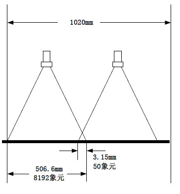
Figure 5 Schematic diagram of the detection scheme
According to the pixel resolution and the moving speed of the film, the integration time can be calculated to be 0.15 ms, and the required line frequency is 6.7 KHz.
On the model of the camera, the Dalsa P2-8K40 camera from Dalsa, Canada, which has a better cost performance, was selected. The line frequency can meet the requirements. Its pixel size is 7μm. The main parameters are shown in the table below.
Table 4 Main performance parameters
name | parameter | ||||
Pixel size | 7*7 ï | ||||
|
| ||||
| 76 DN/ïJ/cm2 | ||||
Highest line frequency flinemax | 9KHz | ||||
Highest data rate fdatamax |
| ||||
Spectral segment | 0.4 to 1.0ï | ||||
| Base CamLink interface | ||||
A/D quantized value | 8bit | ||||
Anti-overflow function | Have | ||||
Lens interface |
| ||||
| 496:1 | ||||
| 2 sets | ||||
6. Lens
Since there is no special restriction on the installation space of the system, there is great flexibility in the choice of the lens. Generally we use a lens with a focal length close to the camera CCD size. For an 8K camera, the pixel size is 7ïm, and the CCD size is 57mm, so it is appropriate to use a lens with a focal length of 60mm.
Based on the CCD size and the actual detection width of each camera, the magnification of the imaging system can be calculated to be 0.11 times. According to the focal length and the magnification, the object distance can be calculated to be 597 mm.
Using Schneider's Apo-Componon 4.0 / 60 lens, Schneider is an internationally renowned lens manufacturer with a very cost-effective lens. At an object distance of 522 mm, the required angle of view is approximately 46.0 ï‚°. The main parameters of the lens are shown in the following table:
Table 5 main parameters of the lens
name | parameter |
focal length | 60mm |
Maximum field of view | |
Relative aperture range | 4.0~ |
Working distance | ∞~0.45 m |
size | 74mm*60.5mm |
weight | 410g |
Quantity | Two |
The distortion rate of this lens is low, the distortion value is less than 0.1% in the 80% imaging range, and the distortion value at the imaging edge is less than 0.2%. The maximum distortion at the edge when using an 8K camera is 0.5mm, so there is basically no need to consider the effects of distortion.
7. Image capture card
A Coreco X64-CL-iPro frame grabber is recommended, with an optional 66MHz and 32M onboard memory. The image capture card supports the Cam Link transmission protocol, which is cheaper and more powerful. The data transmission rate is up to 528MB/sec, which can support the input of two 8K cameras at the same time. This experience has been successfully applied in Lingyun's related projects.
8. Flattening device
Since the film is a flexible material, flattening control is required when acquiring images. If the film is not flat, the transmitted light directional angle changes, causing a sharp change in the gray scale of the image, resulting in missed detection. The recommended method is to install the roller shaft.
9. In order to detect and accurately measure the moving distance in real time, the mark can be sprayed on the hole position after detection.
A synchronization device is required. The general method is to install an encoder that is concentric with the roller shaft so that the encoder input shaft motion is synchronized with the film motion.
10. Computer
The computer is responsible for all management actions of the system and provides a human-computer interaction interface. When a hole is detected, a defect picture can be displayed, and a control command is issued to control the inkjet printer to print the mark.
The system uses two high-resolution (8K) cameras to capture images. According to the line frequency, the data volume of each camera can be calculated to be about 55MB/s, and the amount of image data is very large. Therefore, a high-performance computer is required to complete the processing task. According to the amount of image data, it is recommended to select a PCI-64-bit, 66MHz industrial control computer.
11. Detection algorithm
In the detection algorithm, the detection algorithm is not complicated because it only detects the presence or absence of holes. The image is binarized first, then Blob analysis technology is used, and the reliability is relatively high. Software programming and on-site debugging are around 3-4 weeks.
Third, the system design conclusion
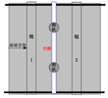
The structure of the system is schematically shown in Figure 6 (side view) and Figure 7 (bottom view). The system works in the visible light spectrum and uses transmission imaging. After the film was flattened by the rolls 1 and 2, images were taken by two 8K line CCD cameras. After the acquisition card is transmitted to the computer, the image processing is performed, and the image features are calculated to determine whether there is a hole. If present, the computer sends a control signal to complete the detection of the surface quality of the film. If the temperature of the on-site working environment is high, consider cooling down the CCD camera to ensure the normal operation of the camera.

Http://news.chinawj.com.cn Editor: (Hardware Business Network Information Center) http://news.chinawj.com.cn
Thin Tape Hydraulic Jack,Thin Tape Lifting Jack,Electric Hydraulic Jack,Thin Belt Hydraulic Jack
Taizhou Juhuan Lifting Protection Equipment Co., Ltd , https://www.jsjoba.com